
Добрый день. Ну и хватит о добром. Начитавшись и насмотревшись на всем известный индукционный генератор по схеме ZVC драйвера, решил сделать нечто похожее для закалки небольших металлических предметов, в гаражную автомастерскую и для плавки свинца на грузила. Схема стандартная, обычный высокочастотный мультивибратор, который повторили уже сотни человек.
Схема ZVC драйвера
Стандартный вариант генератора

Усиленный вариант схемы

Но видно мне войти в их число не судьба…


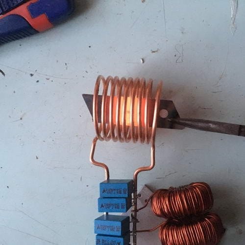
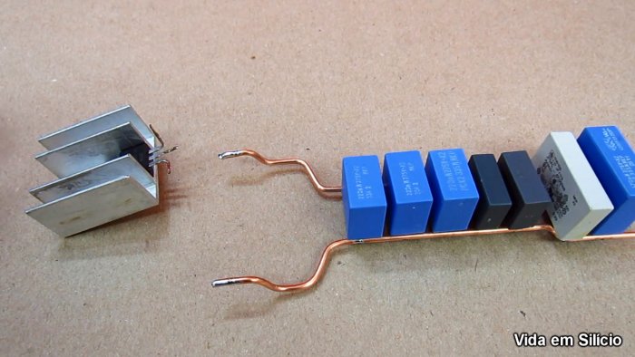
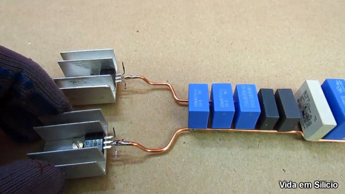
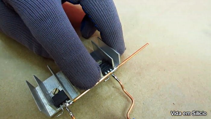
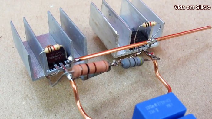
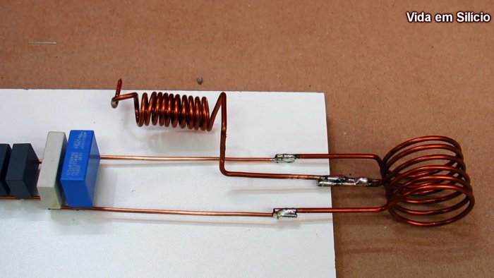
Были куплены все необходимые детали — новые полевые транзисторы, новые фаст диоды и стабилитроны. Всё перед пайкой было испытано на транзистор-тестере, в том числе для определения правильной цоколёвки.


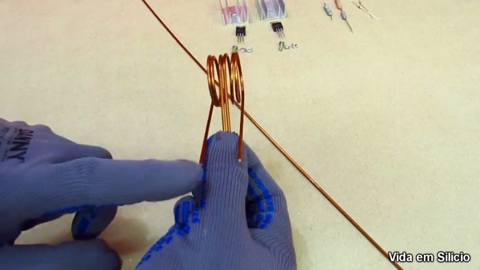
Была собрана шикарная катушка из чистой меди диаметром 5 мм. Но работать сей девайс упорно отказывался.


Подозрение пало на дросселя, которые большинство радиолюбителей рекомендует мотать на желтых порошковых кольцах от БП АТХ.


Добыча искомых и установка также оказалась безрезультативной — индукционный нагреватель металлов как не работал раньше, так и не собирался работать дальше. Подключение различных вариантов катушек совместно с конденсаторами разной емкости картину не изменили — «открывает рыба рот, но не слышно что поёт», то есть транзисторы открываются, ток тянут, а генерации не происходит…

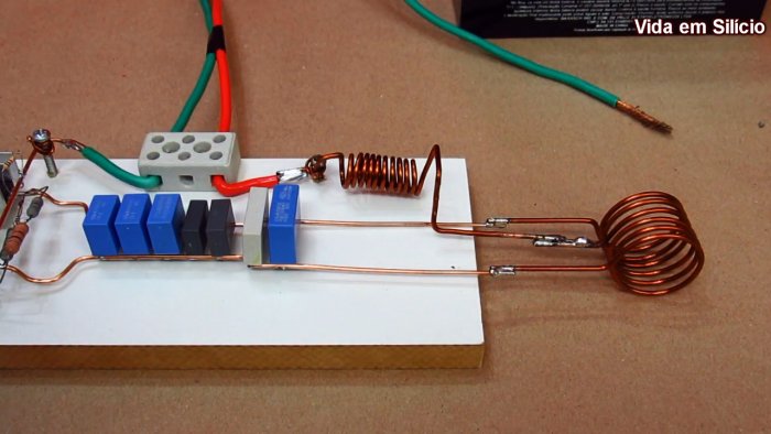
В конце концов всё это изрядно надоело, многодневные танцы с бубном закончились, и пришлось с поклоном идти к китайцам на ихний Алиэкспресс, заказывать за 7 долларов готовый модуль генератора.


Спустя 2 недели эта штука была доставлена курьером прямо на дом и после подключения к компьютерному блоку питания на 12 В успешно заработала.


Причём она работала и от 5-ти вольт, и с маленькой штатной катушкой, и с большой самодельной, в общем генерировала мощное электромагнитное поле во всех позах (с теми же деталями и схемой). Раскаляет 3 мм штырь до красна за 20 секунд. С железкой 6 мм возится несколько минут, при этом жутко греется само (в основном транзисторы и катушка).


На что тут грешить — даже не знаю. Может конденсаторы не те, может транзисторы… В любом случае факт остается фактом: промышленная плата заработала, а самодельная нет. Так что кто хочет — может смело кинуть в меня куском канифоли, другие — посочувствовать, третьи сами попробовать собрать этот индукционник и написать в комментариях о результатах…
Простой индукционный нагреватель своими руками
Приветствую, радиолюбители-самоделкины!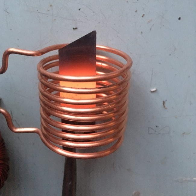
Сейчас на кухнях довольно часто можно встретить новый тип варочных плит — индукционные. В отличие от газовых и простых электрических, в них не нагревается конфорка, не горит с высокой температурой газ, ведь электрическая энергия в таких плитах поступает «напрямую» к разогреваемой посуде, не нагревая ненужные посторонние части плиты. Работает это следующим образом — специальный индуктор создаёт в толще металла посуды сильные вихревые токи, которые и разогревают металл. Помимо кухонных плит, такая технология используется в разных областях промышленности для нагрева и плавки металла. Возможно, на первый взгляд индукционный нагрев выглядит сложно и очень труднореализуемо в домашних условиях, но на самом деле, схема простого индукционного нагревателя не содержит дорогих либо редких деталей, собрать её под силу каждому радиолюбителю. Мощность такой схемы достаточна для того, чтобы раскалить до красна небольшие металлический предметы — лезвия канцелярского ножа, отвёртки, гвозди.
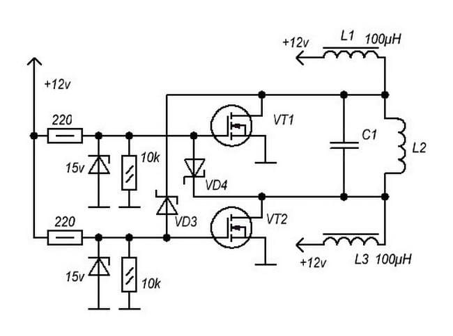
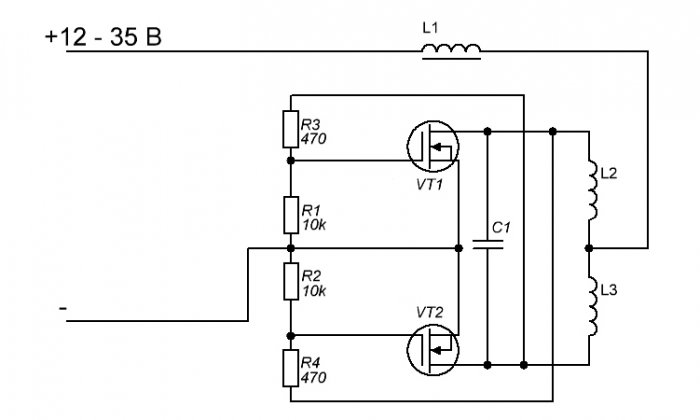
На самом деле, данная схема является довольно универсальной, на её основе также строят различные высоковольтные генераторы и прочие устройства, где требуется генерация высокочастотных импульсов. В интернете эту схему можно найти по названию «ZVS-драйвер». Рассмотрим более подробно все элементы схемы, определим возможные замены и отметим некоторые нюансы. Напряжение питания на схеме указано 12 В — это минимальное напряжение, которым можно питать данную схему. Максимальная граница напряжения питания зависит от мощности выбранных транзисторов и может составлять 50В. Чем больше напряжение питания, тем, соответственно, больше будет мощность индукционного нагревателя, тем быстрее он будет разогревать металл. Данная схема, особенно при разогреве массивных предметов, потребляет большой ток (до 10А), поэтому важно обеспечить её питание от источника соответствующей мощности. Неплохо для этого подойдут, например, блок питания компьютера или ноутбука, имеющие на выходе напряжения 12 и 19Вт соответственно.
Резисторы номиналами 220 Ом должны быть рассчитаны на мощность как минимум в 1 ватт, иначе возможен их чрезмерный нагрев. После этих резисторов на схеме можно увидеть стабилитроны, имеющими маркировку на схеме «15 v». Здесь можно применить любые стабилитроны на напряжение стабилизации в пределах от 12 до 15В, они нужны для того, чтобы на затворы полевых транзисторов не попало высокое напряжение (более 20В на затворе будет смертельным для полевого транзистора). Также на схеме можно увидеть диоды VD3 и VD4, подключенные к затворам транзисторов — в качестве них можно применить практически любые быстродействующие (обозначаются как ultra fast) диоды, например, UV4007, HER102, FR103. Особое внимание стоит уделить выбору транзисторов для данной схемы. На малой мощности с низким напряжением питания будут без проблем работать практически любые полевые транзисторы из ряда IRFZ44, IRF3205, 50N06 и им подобные по характеристикам. Но при использовании индукционного нагревателя при напряжении питания выше 12В рекомендуется поставить более мощные транзисторы, например IRFP250, IRFP260 либо им аналогичные. Ключевыми параметрами для транзисторов здесь будут максимальное напряжения сток-исток и максимальный ток. На схеме присутствуют дроссели L1 и L3, подключенные одним концом к плюсу питания. Можно найти готовые дроссели, рассчитанные на большой ток (как минимум 2-3А, но чем больше, тем лучше), имеющие индуктивность в диапазоне 47-200 мкГн, так и намотать дроссели самому. Для этого нужно взять кольцо из порошкового железа (оно имеет жёлтый цвет), и намотать на нём примерно 30-40 витков толстого медного провода. Найти кольца жёлтого цвета можно в компьютерных блоках питания, кроме них чуть хуже, но также подойдут обычные ферритовые кольца.
Колебательный контур C1 L2, пожалуй, самая важная часть схемы — именно эти элементы задают частоту колебания схемы. Катушка L2 — непосредственно сам индуктор, катушка большого размера из толстого медного провода, внутрь которой помещается нагреваемый предмет. Её диаметр может составлять от 1 до 5 см, в зависимости от размеров предмета, который нужно будет разогревать. Следует также учитывать, что чем больше будет размер катушки относительно размера нагреваемого объекта — тем менее эффективной будет работа данной схемы. В идеальном случае объект должен помещаться в катушку, не оставляя больших зазоров по краям, до витков. Для намотки можно использовать как изолированный медный провод, так и медные трубки либо шины. Количество витков может варьироваться в пределах от 6 до 12. Чем больше будет напряжение питания, тем большее количество витков следует выбирать.
Через конденсатор С1 в данной схеме будут протекать довольно значительные токи, а потому необходимо использовать неполярные плёночные конденсаторы и низким внутренним сопротивлением (ESR). Ёмкость С1 может варьироваться в пределах 0,68 — 1 мкФ, её можно будет подбирать для достижения наилучшей эффективности работы схемы, оценивая скорость нагрева. Для того, чтобы снизить внутреннее сопротивление С1, можно включить параллельно несколько конденсаторов — это наиболее предпочтительный вариант. Например, 6-10 конденсаторов по 0,1 мкФ каждый дадут как раз нужную ёмкость, а внутреннее сопротивление такой батареи конденсаторов будет значительно меньше, чем у одного конденсатора.
Ниже представлены осциллограммы в разных частях схемы.
На затворе транзистора:
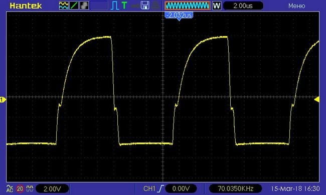
Сток-исток транзистора:
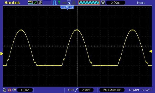
На самой катушке индуктора:
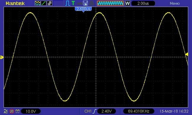
Можно увидеть, что амплитура на катушке индуктора составляет около 70 вольт, и это при том, что напряжение питания схемы составляет всего 11В.
Преимуществом данной схемы является её простота — для сборки даже не обязательно изготавливать печатную плату. Смонтировать все элементы можно прямо на выводах индуктора, если он выполнен из жёсткого провода, то и конструкция будет обладать нужной жёсткостью и надёжностью. Батарея конденсаторов припаивается прямо на толстые выводы.
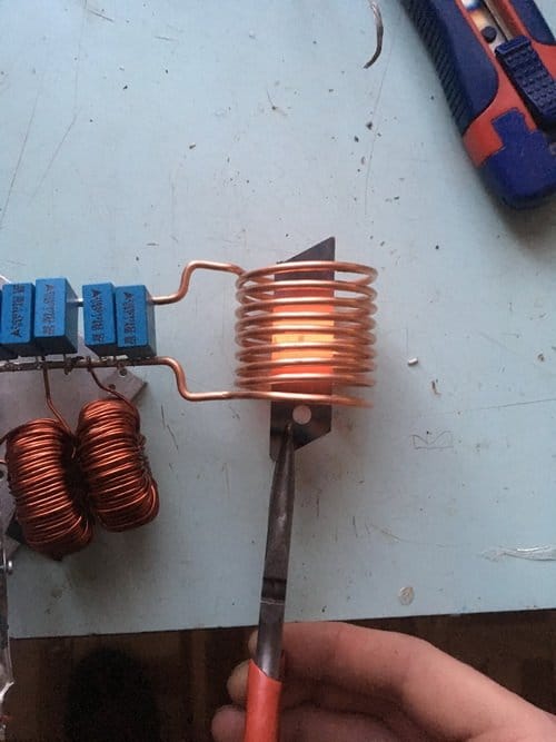
Ещё одним преимуществом данной схемы является её большой КПД — практически вся мощность, потребляемая от источника, уходит в нагрев объекта, а потому транзисторы нагреваются лишь слегка и не требуют массивных радиаторов. Тестовый запуск схемы можно проводить и вовсе без радиаторов, но для долговременной работы они обязательны. Также следует заметить, что ток потребления в этой схеме большой лишь во время нагрева — когда внутрь катушки-индуктора помещён металлический объект. На холостом же ходе схема потребляет небольшой ток, максимум несколько сотен миллиампер. Ниже представлено несколько фотографий раскалённого лезвия ножа, нагретого таким индукционным нагревателем. Удачной сборки!
Источник (Source) Становитесь автором сайта, публикуйте собственные статьи, описания самоделок с оплатой за текст. Подробнее здесь.
ПРОСТОЙ ИНДУКЦИОННЫЙ НАГРЕВАТЕЛЬ
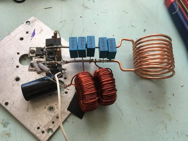
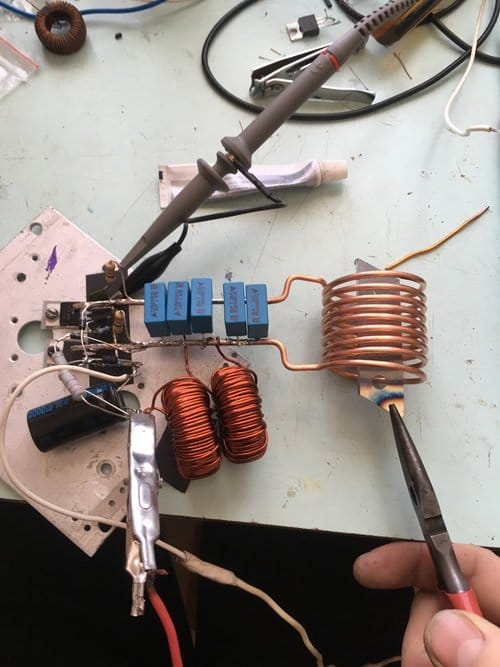
Приветствую пользователей сайта Радиосхемы. Недавно у меня появилась идея сделать индукционный нагреватель. На просторах интернета были найдены несколько схем для построения устройства. Из них выбрал самую, на мой взгляд, простую по сборке и настройке, и главное — реально рабочую.
Схема устройства

Список деталей
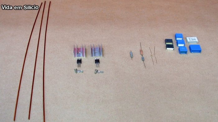
1. Полевой транзистор IRFZ44V 2 шт.
2. Диоды ультра быстрые UF4007 или UF4001 2 шт.
3. Резистор на 470 Ом на 1 или 0.5 Вт 2 шт.
4. Конденсаторы плёночные
1) 1 мкФ на 250в 3 шт.
2) 220 нФ на 250в 4 штуки.
3) 470 нФ на 250в
4) 330 нФ на 250в
5. Провод медный диаметром 1.2 мм.
6. Провод медный диаметром 2 мм.
7. Кольца от дросселей компьютерном блоке питания 2 шт.
Сборка устройства
Задающая часть нагревателя выполнена на полевых транзисторах IRFZ44V. Распиновка транзистора IRFZ44V.

Транзисторы нужно поставить на большой радиатор. Если устанавливать транзисторы на один радиатор то транзисторы нужно установить на резиновые прокладки и пластмассовые шайбочки чтобы не было замыкания между транзисторов.

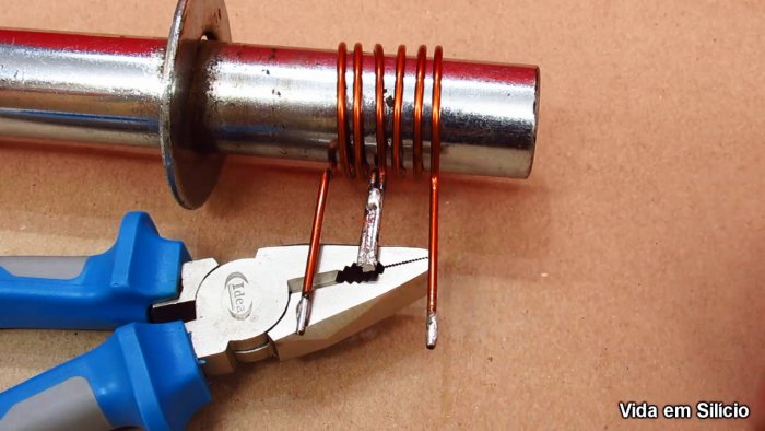
Дросселя намотаны на кольцах от компьютерных БП. Сделанные из порошкового железа. Проводом 1,2 мм 7-15 витков.

Батарея конденсаторов должна быть на 4.7 мкФ. Желательно использовать не один конденсатор, а несколько конденсаторов. Конденсаторы должны быть подключены параллельно.

Катушка нагревателя сделана на проводе диаметром 2 мм 7-8 витков.

После сборки устройство работает сразу. Питается устройство от аккумулятора 12 вольт 7.2 А/ч. Напряжение питания устройства 4.8-28 вольт. При продолжительной работе перегреваются: батарея конденсаторов, полевые транзисторы и дросселя. Потребление тока при холостом ходу 6-8 Ампер.

При внесении в контур металлического предмета потребление тока сразу увеличивается до 10-12 А.

Фото готового устройства смотрите далее.

Видео работы индукционного нагревателя
Далее можно оформить прибор в подходящий красивый корпус и использовать для различных опытов. С мощностью и размером катушки лучше поэкспериментировать, чтоб достичь наилучшего эффекта. Автор статьи 4ei3
Форум
Обсудить статью ПРОСТОЙ ИНДУКЦИОННЫЙ НАГРЕВАТЕЛЬ
Индукционный нагреватель незаменимая вещь для кузнецов, токарей, слесарей и домашних мастеров. С его помощью всегда легко и быстро можно нагреть и даже расплавить металл, вам не нужны дорогие теплоносители, такие, как уголь и газ, достаточно подключить к прибору электричество. Происходит бесконтактный нагрев металла токами высокой частоты, по научному волнами радиочастотного диапазона. Прибор широко применяют для термообработки, закалки и гибки деталей, бесконтактной плавки, пайки и сварки, металлов. В ювелирном деле для термической обработки мелких деталей. В медицине для дезинфекции медицинского инструмента. В автосервисе слесаря нагревают заржавевшие гайки. Так же индуктор устанавливают в индукционных котлах, применяемых для отапливания жилых помещений.
На этом рисунке изображена рабочая схема индукционного нагревателя, который вы легко можете сделать своими руками.
Скачать схему индукционного нагревателя
Устройство состоит из задающего генератора высокой частоты собранного на двух мощных полевых транзисторах. Рабочее напряжение генератора зависит от мощности установленных полевых транзисторов. С транзисторами IRFP250 устройство можно питать напряжением от 12 до 30 вольт. А если установить транзисторы IRFP260, тогда напряжение питания можно поднять от 12 до 60 вольт.
Мощность индуктора заметно возрастет, температура нагрева металла поднимется более 1000 градусов, что позволит плавить металлы. В процессе работы транзисторы будут очень сильно нагреваться, поэтому их надо установить на большие радиаторы и поставить мощный вентилятор. На холостом ходу индуктор потребляет не менее 10А, а в рабочем состоянии не менее 15А, соответственно требуется очень мощный блок питания минимум на 20А.
На этом рисунке изображена печатная плата индукционного нагревателя.
Скачать печатную плату индукционного нагревателя в формате lay
Так же вам понадобятся резисторы R1, R2 на 10К мощностью 0.25 Ватт. Резисторы R3, R4 с сопротивлением 470 Ом не менее 2 Ватт. Диоды D1, D2 ультрабыстрые UF4007 или другие аналогичные на максимальный ток до 1А. Стабилитроны VD1, VD2 мощностью не менее 5 Ватт с напряжением стабилизации 12В например 1N5349 и другие. Дроссели L1, L2 размером 27х14х11 мм желтого цвета с белой полосой я вытащил из компьютерных блоков питания. На каждый дроссель надо намотать 25 витков медного провода диаметром 1 мм желательно в лаковой изоляции, если не найдете, подойдет одножильный провод в полихлорвиниловой изоляции на скорость сильно не влияет.
Конденсаторы С1-С16 металлоплёночные 0.33 мкФ 630В, соединяются параллельно рядами 4х4, в блоке всего шестнадцать штук. С меньшим рабочим напряжением лучше не ставить, будут сильно греться. Между конденсаторами оставляйте небольшое расстояние для хорошего охлаждения потоком воздуха.
Дроссели решил приклеить силиконовым герметиком, чтобы не болтались.
Важную деталь нагревателя, индуктор я сделал из медной трубки диаметром 6 мм длинною 1 метр. Купить такую можно в любом автомагазине типа «Газовщик» и там где торгуют газо-балонным оборудованием для автомобилей. Медную трубку наматываем на кусок полипропиленовой трубы внешним диаметром 40 мм, такая труба используется в пластиковом отоплении. Делаем пять витков, расстояние между верхним краем первого витка и нижним краем пятого витка должно быть 40 мм. Концы трубы изгибаем, как на рисунке и прикрепляем к радиаторам с помощью двух клемных колодок для провода сечением 16 мм².
В процессе работы индуктор будет сильно нагреваться от раскаленной детали, что может привести к повреждению медной трубки, поэтому надо сделать охлаждение. На концы медной трубки я одел силиконовые трубки и подключил насос омывателя лобового стекла автомобиля. Насос от ВАЗ 2114 и силиконовые трубки купил в автомагазине. Получилась нормальная водяная система охлаждения.
Чтобы охлаждать радиаторы и блок конденсаторов поставил мощный вентилятор от процессора. Для питания от 12 вольт такого охлаждения вполне достаточно. Если захотите поднять напряжение от 12 до 60 вольт, чтобы получить максимальную мощность от индукционного нагревателя, поставьте более мощные радиаторы и более производительный вентилятор, например от отопителя салона ВАЗ 2107. Желательно сделать металлическую шторку оберегающую нагреваемую деталь и медный индуктор от потока нагнетаемого вентилятором холодного воздуха.
Поскольку индукционный нагреватель потребляет большой ток около 20А, все дорожки на печатной плате следует усилить медной проволокой, напаянной сверху.
А теперь самое интересное… Испытания индукционного нагревателя я проводил от двенадцати вольтового автомобильного аккумулятора. Другого источника питания способного выдавать большие токи у меня просто нет. Лезвие от канцелярского ножа нагрелось до красна за 10 секунд. А это хороший результат, если учесть, что индуктор запитан всего от двенадцати вольт!
Друзья! Если хотите собрать индукционный нагреватель своими руками. Мой вам совет… Сразу ставьте полевые транзисторы IRFP260, большие радиаторы и мощный вентилятор от отопителя салона ВАЗ 2107, для питания индуктора обязательно используйте мощный источник питания лучше всего начиная от 24В до 60В с силой тока минимум на 20А.
Радиодетали для сборки индукционного нагревателя
- Транзисторы Т1, Т2 IRFP250 лучше IRFP260 2 шт.
- Резисторы R1, R2 10K 0.25W 2 шт. R3, R4 470R 2W 2 шт.
- Диоды D1, D2 ультрабыстрые UF4007 2 шт. или аналогичные
- Стабилитроны VD1, VD2 на 12V 1W 1N5349 или аналогичные 2 шт.
- Конденсаторы C1-C16 0.33mf 630V 16 шт.
- Дроссели от компьютерного БП желтые с белой полосой, размер 27х14х11 мм 2 шт.
- Колодка клемная для провода сечением 16 мм² 2 шт.
- Провод медный в лаковой изоляции d=1 мм длина 2 метра
- Трубка медная d=6 мм, длина 1 метр
- Радиатор чем больше, тем лучше 2 шт.
- Насос омывателя лобового стекла от ВАЗ 2114 1 шт.
- Трубка силиконовая 2 метра
- Вентилятор чем мощнее, тем лучше. Рекомендую от отопителя салона ВАЗ 2107 1 шт.
Друзья, желаю вам удачи и хорошего настроения! До встречи в новых статьях!
Рекомендую посмотреть видеоролик о том, как сделать индукционный нагреватель своими руками
Преобразователи напряжения, Электроника 500 ватт, бесконтактный нагрев металла, для дома, для квартиры, индуктор, индукционное отопление, индукционный нагрев, индукционный нагреватель, мини горн, мощный обогреватель, на полевых транзисторах, нагреватель для металла, своими руками, токи высокой частоты, электромагнитная индукция, электронагреватель
Индукционный водонагреватель своими руками: схема
Прибор представляет собой трансформатор, имеющий две обмотки: первичную и вторичную. Первый контур преобразует электрическую энергию в вихревые токи, тем самым создает индукционное поле направленного действия, что и обеспечивает индукционный нагрев. На вторичном контуре преобразованная энергия передается теплоносителю (в нашем случае – это вода).
Важно учитывать тип материала, из которого изготовлена обмотка. Так, в бытовых моделях чаще всего используется медный провод
Такой материал хорошо подойдет для нагрева воды в котлах.
Кроме трансформатора в устройстве присутствует генератор и насос (необязательно).
Схема простого индукционного водонагревателя. Как видно, прибор имеет довольно простую конструкцию и малое количество элементов.
Узлы и детали теплогенератора
Устройство включает в себя:
- генератор переменного тока, который увеличивает частоту тока;
- индуктор, трансформирующий электроэнергию в магнитную энергию, представляет собой катушку из медной проволоки;
- нагревательный элемент, чаще всего его роль играет металлическая труба.
Благодаря такой конструкции передача энергии осуществляется практически без потерь. КПД достигает 98%.
Принцип работы
Индукционный водонагреватель состоит из генератора, катушки и сердечника, последний нагревается за счет электромагнитной энергии
Прибор преобразует электрическую энергию в электромагнитную. Последняя, в свою очередь, воздействует на сердечник (трубу), который нагревается и передает воде тепловую энергию. Преобразовывает все эти энергии индуктор, состоящий из катушки и сердечника. Генератор используется для повышения частоты тока, так как со стандартной частотой в 50 Гц сложно добиться высокого нагрева.
В заводских моделях частота тока достигает 1 кГц.
Описание и преимущества техники
Принцип работы индукционных нагревателей основывается на выделении тепла металлами при пропускании через них тока. При подаче напряжения на токопроводящий контур образуется магнитное поле и индукционный ток, который выделяет большое количество тепла. Сегодня на основе этой технологии изготавливаются различные электрические нагреватели, которые одновременно сочетают компактные размеры и отличаются великолепной мощностью. Благодаря простоте конструкции таких установок изготовить их самостоятельно не составит труда.
Одним из плюсов данного нагревателя является почти 100% КПД
К преимуществам индукционного нагрева можно отнести следующее:
- Высокая мощность.
- Возможность работы в различных средах.
- Полная э
Как сделать простой индукционный нагреватель
Индукционный нагреватель – это устройство, которое работает используя магнитные свойства металлов. Сделать его своими руками очень просто. Устройство будет полезно не только для изучения основ электротехники, но и в практических целях, например, для закалки деталей. После небольшой доработки можно использовать для сборки домашнего отеплителя.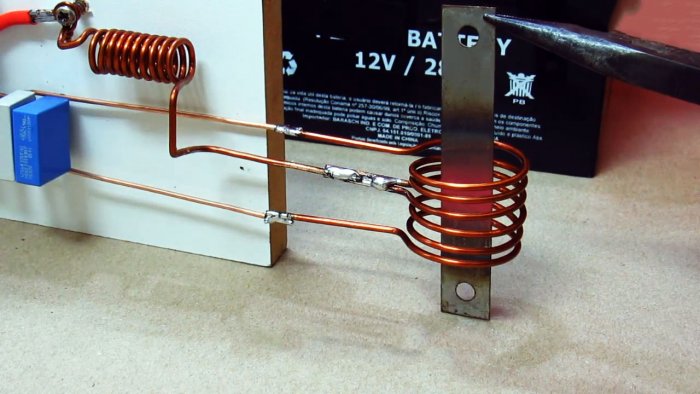
Необходимые детали
Для сборки индукционного нагревателя нам потребуется:
- медная проволока диаметром 1-1,5 мм;
- 2 полевых транзистора IRF44N с радиаторами;
- набор конденсаторов, общей емкостью 2-2,5 мкф;
- по 2 резистора сопротивлениями 10 Ком и 470 Ом.
К деталям не предъявляется строгих требований. Вместо указанных можно использовать любые N-канальные полевики с аналогичной цоколевкой и ток не менее 10 А. Мощность рассеивания входных резисторов R3 и R4– 2 Вт, с разбросом по сопротивлению 100 – 620 Ом.
Схема индукционного нагревателя представлена ниже.
Процесс сборки индукционного нагревателя
Схема довольно проста, поэтому будем собирать ее навесным монтажом. Все элементы впоследствии закрепим на небольшом деревянном бруске.
Подготовим детали. Если под рукой не окажется резисторов нужных номиналов, можно соединить два последовательно.
Помните! При последовательном соединении резисторов, их мощность остается неизменной. Если вы заменяете R3 или R4 несколькими резисторами, убедитесь, что все детали имеют требуемую мощность рассеивания.
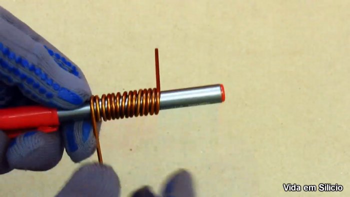
Изготовим индуктор. На гладкий стальной стержень диметром 70 мм, намотаем 3 витка медного провода, оставив с концов прямые отрезки под выводы. Нужно сделать две такие катушки.
Спаяем вместе два вывода катушек, которые образуют общую точку.
Для изготовления катушки индуктивности L1 нужен стержень тоньше, диаметром 20-25 мм. Намотаем 10 витков провода. Для удобства монтажа сделаем так, чтобы выводы были расположены в противоположных направлениях.
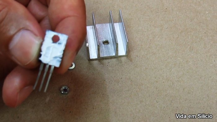
Установим транзисторы на радиаторы, смазав внутреннюю часть корпуса термопастой.
Соберем конденсаторную батарею необходимой емкости, соединив их параллельно. В качестве проводников используем такой же медный провод, которым проводили намотку индуктора.
Отформуем выводы транзисторов: крайнюю левую ножку аккуратно изогнем влево, крайнюю правую – вперед.
Соединим центральные выводы транзисторов с конденсаторной батареей.
Соединим исток первого транзистора (крайний правый вывод) с истоком второго перемычкой. Оставим небольшой отрезок провода для дальнейшего монтажа.
Подпаяем резисторы согласно схеме.
С другой стороны конденсаторной батареи устанавливаем индуктор, средний вывод которого соединяем с катушкой индуктивности.
Установим клеммник питания. «Плюсовой» провод пойдет на свободный конец катушки индуктивности, «минус» соединяем с перемычкой между правыми ножками транзисторов.
Устройство готово к работе. Если поместить в катушку индуктора металлический предмет, он быстро нагреется. Сама же катушка нагреваться не будет.
Смотрите видео
Проточный индукционный водонагреватель своими руками
Прежде чем приступать к монтажу, вам необходимо запастись необходимыми деталями. Так, лучшим вариантом будет сварочный высокочастотный инвертор, плавно изменяющийся диапазон силы тока. Такое устройство обойдется дешевле всего. Более дорогим вариантом станет трехфазный трансформатор, являющийся источником питания переменного тока для индуктора водонагревателя. В таком случае стоит использовать катушку на 50-90 витков, а в качестве материала взять медную проволоку с диаметром 3 или более миллиметров.
В качестве сердечника можно использовать как металлическую, так и полимерную трубу вместе с проволокой (используется как нагревательный элемент). В последнем случае толщина стен не должна быть менее 3 мм, чтобы спокойно выдерживать высокие температуры.
Для сборки водонагревателя вам понадобятся: кусачки, отвертки, паяльник и сварочный аппарат, если используется металлическая труба.
Монтаж индукционного нагревателя воды
Обмотайте трубу медной проволокой, сделав около 90 витков.
Вариантов сборки устройства существует множество. Предлагаем попробовать собрать прибор по следующей схеме:
- Подготовьте рабочее место, материалы и инструменты.
- Зафиксируйте небольшой отрезок полимерной трубы (не забывайте, что минимальная толщина стенки должна составлять 3 мм).
- Обрежьте торцы сердечника, чтобы осталось 10 см в запасе провода для отводов.
- На нижнем отводе смонтируйте уголок. В дальнейшем сюда следует подключить обратку от отопления (если нагреватель используется в качестве котла).
- Плотно уложите рубленый провод вокруг трубы. Необходимо сделать не менее 90 витков.
- Установите на верхнем патрубке тройник, через который будет выходить горячая вода.
- Смонтируйте защитный контур устройства. Его можно изготовить как из полимера, так и из металла.
- Подключите к клеммам водонагревателя медную проволоку, затем заполните сердечник водой.
- Проверьте работоспособность индуктора.
Схема и порядок сборки
Электрическая схема индукционного нагревателя воды. (Для увеличения нажмите)Конструирование индукционного нагревателя своими руками должно происходить согласно следующим последовательным этапам:
Нагревательный элемент. Один из торцов пластиковой трубы фиксируется металлической сеткой. Затем нержавеющая проволока нарезается кусачками на небольшие отрезки, которые плотно помещаются внутри трубы
При этом очень важно не допускать пустот. Второй торец трубы также фиксируется металлической сеткой.
Индуктор
Поверх пластиковой трубы наматывается медная проволока, которая будет создавать вихревые потоки. При этом очень важно знать, что количество витков должно быть не менее 90.
Инвертор. Этот прибор конструируется на тиристорах, которые позволяют эффективно преобразовывать обычную электроэнергию в высокочастотный ток. Тиристорный инвертор является самым важным компонентом индукционного нагревателя. Стоит также отметить, что у тиристорного преобразователя электронное управление, которое позволяет плавно регулировать подачу тока, а также надежно защищает от аварийных ситуаций.
Подключение. Когда индукционный нагреватель воды полностью смонтирован, то с помощью шаровых кранов и переходников он непосредственно подключается к отопительной системе.
Смотрите видео, в котором специалист подробно показывает процесс сборки индукционного нагревателя воды своими руками:
Идея №2 – Более мощный аппарат
Чтобы сделать мощный индукционный котел своими руками, необходимо всего лишь уметь пользоваться сваркой. На самом деле технология сборки не слишком сложная и с ней сможет справиться любой электрик-самоучка, в чем Вы и убедитесь после прочтения.
Итак, из материалов Вам понадобятся:
90000 How to Design an Induction Heater Circuit 90001 90002 The article explains a step by step tutorial regarding designing your own homemade basic induction heater circuit, which can be also used as an induction cooktop. 90003 90004 Basic Induction Heater Concept 90005 90002 You might have come across many DIY induction heater circuits online but nobody seem to have addressed the crucial secret behind implementing a perfect and a successful induction heater design. Before knowing this secret it would be important to know the basic working concept of an induction heater.90003 90002 An induction heater is actually an extremely «inefficient» form of electrical transformer, and this inefficiency becomes its main advantageous feature. 90003 90002 We know that in an electrical transformer the core needs to be compatible with the induced frequency, and when there’s an incompatibility between frequency and the core material in a transformer, it results in the generation of heat. 90003 90002 Fundamentally an iron cored transformer will require a lower range of frequency around 50 to 100Hz, and as this frequency is increased the core may shown a tendency of getting hotter proportionately.That implies, if the frequency is increased to a much higher level may be over 100kHz would result in the generation of extreme heat within the core. 90003 90002 Yes, this is exactly what happens with an induction heater system where the cooktop acts like the core and therefore is made up of iron material. And the induction coil is subjected to a high frequency, together this results in the generation of a proportionately intense amount of heat on the vessel. Since the frequency is optimized at significantly high level ensures a maximum possible heat on the metal.90003 90002 Now let’s proceed and learn the important aspects that may be required for designing a successful and technically correct Induction heater circuit. The following details will explain this: 90003 90004 What you will Need 90005 90002 The two bare basic things required for building any induction cookware are: 90003 90002 1) A bifilar coil. 90003 90002 2) An adjustable frequency generator circuit 90003 90002 I have already discussed a few induction heater circuits in this website, you can read them below: 90003 90002 Solar Induction Heater Circuit 90003 90002 Induction Heater Circuit Using IGBT 90003 90002 Simple Induction Heater Circuit — Hot Plate Cooker Circuit 90003 90002 Small Induction Heater Circuit for School Project 90003 90002 All the above links have the above two things in common, that is they have a work coil and a driver oscillator stage.90003 90004 Designing the Work Coil 90005 90002 For designing an induction cookware, the work coil is supposed to be flat in nature, therefore it must be bifilar type with its configuration, as shown below: 90003 90002 The bifilar coil type design shown above can be effectively implemented for making your homemade induction cookware. 90003 90002 For optimum response and low heat generation within the coil make sure the wire of the bifilar coil is made using many thin strands of copper instead of a single solid wire.90003 90002 Thus, this becomes the work coil of the cookware, now the ends of this coil simply needs to be integrated with a matching capacitor and a compatible frequency driver network, as shown in the following figure: 90003 90048 Designing the H-Bridge Series Resonant Driver Circuit 90049 90002 So far the information should have enlightened you regarding how to configure a simple induction cookware or an induction cooktop design, however the most critical part of the design is how to resonate the coil capacitor network (the tank circuit) into the most optimal range so that the circuit works at the most efficient level.90003 90002 Enabling the coil / capacitor tank circuit (LC circuit) to operate at their resonance level requires the inductance of the coil and the capacitance of the capacitor to be matched perfectly. 90003 90002 This can happen only when the reactance of both the counterparts are identical, that is the reactance of the coil (inductor) as well as the capacitor are approximately the same. 90003 90002 Once this is fixed you can expect the tank circuit to operate at its natural frequency and the LC network reaching the resonance point.This is called a perfectly tuned LC circuit. 90003 90002 This concludes the basic induction heater circuit designing procedures 90003 90002 You may be wondering regarding what is resonance of an LC circuit. ?? And how this may be calculated quickly for completing a specific induction heater design? We will comprehensively discuss this in the following sections. 90003 90002 The above paragraphs explained the fundamental secrets behind developing a low cost yet effective induction cooktop at home, in the following descriptions we will see how this can be implemented by specifically calculating its crucial parameters such the resonance of its tuned LC circuit and the correct dimension of the coil wire for ensuring an optimal current handling capacity.90003 90048 What is Resonance in Induction Heater LC Circuit 90049 90002 When the capacitor within a tuned LC circuit is momentarily charged, the capacitor tries to discharge and dump the accumulated charge over the coil, the coil accepts the charge and stores the charge in the form of magnetic field. But as soon as the capacitor has discharged in the process, the coil develops an almost equivalent amount of charge in the form of magnetic field and it now tries to force this back inside the capacitor, although with an opposite polarity.90003 90002 90069 Image courtesy: 90070 90003 90072 90072 90002 Wikipedia 90003 90002 The capacitor is again forced to charge but this time in the opposite direction, and as soon as it’s fully charged, it yet again tries to empty itself across the coil, and this results in a back and forth sharing of charge in the form of an oscillating current across the LC network. 90003 90002 The frequency of this oscillating current becomes the resonance frequency of the tuned LC circuit. 90003 90002 However due to inherent losses the above oscillations eventually die out in the course of time, and the frequency, the charge all come to an end after sometime.90003 90002 But if the frequency is allowed to sustain through an external frequency input, tuned at the same resonance level, then that could ensure a permanent resonance effect being induced across the LC circuit. 90003 90002 90085 At resonance frequency we can expect the amplitude of the voltage oscillating across the LC circuit to be at the maximum level, resulting in the most efficient induction. 90086 90003 90002 Therefore we can imply that, to implement a perfect resonance within an LC network for an induction heater design we need to ensure the following crucial parameters: 90003 90002 1) A tuned LC circuit 90003 90002 2) And a matching frequency to sustain the LC circuit resonance.90003 90002 This can be calculated using the following simple formula: 90003 90002 90069 F = 1 ÷ 90070 90069 2π 90070 x 90069 √LC 90070 90003 90002 where L is in Henry and C is in Farad 90003 90002 If you do not want to go through the hassles of calculating the resonance of the coil LC tank through formula, a much simpler option could be to use the following software: 90003 90002 LC Resonant Frequency Calculator 90003 90002 Or you may also build this Grid dip meter for identifying and setting the resonance frequency.90003 90002 Once the resonance frequency is identified, it’s time to set the full-bridge IC with this resonance frequency by suitably selecting the Rt, and Ct timing components. This may be done by some trial and error through practical measurements, or through the following formula: 90003 90002 The following formula can be used for calculating the values of Rt / Ct: 90003 90002 f = 1 / 1.453 x Rt x Ct where Rt is in Ohms and Ct in Farads. 90003 90004 Using Series Resonance 90005 90002 The induction heater concept discussed in this post uses a series resonant circuit.90003 90002 When a series resonant LC circuit is employed, we have inductor an (L) and a capacitor (C) connected in series, as shown in the following diagram. 90003 90002 The total voltage 90125 V 90126 applied across the series LC will be the sum of the voltage across the inductor L and the voltage across the capacitor C. The current flowing through the system will be equal to the current that’s flowing through the L and the C components. 90003 90002 V = VL + VC 90003 90002 I = IL = IC 90003 90002 The frequency of the applied voltage affects the reactances of the inductor and the capacitor.As frequency is increased from a minimum value to a higher value, the inductive reactance XL of the inductor will proportionately increase, but XC which is the capacitive reactance will decrease. 90003 90002 However, while the frequency is being increased there will be a particular instance or threshold when the magnitudes of the inductive reactance and the capacitive reactance will be just equal. This instance will be the resonant point of the series LC, and the frequency can be set as the resonant frequency.90003 90002 Therefore, in a series resonant circuit, the resonance will occur when 90003 90002 XL = XC 90003 90002 or, ωL = 1 / ωC 90003 90002 where ω = angular frequency. 90003 90002 Evaluating the value of ω gives us: 90003 90002 ω = ωo = 1 / √ LC, which is defined as the resonant angular frequency. 90003 90002 Substituting this in the previous equation and also converting the angular frequency (in radians per second) into frequency (Hz), we finally get: 90003 90002 fo = ωo / 2π = 1 / 2π√ LC 90003 90002 90085 fo = 1 / 2π√ LC 90086 90003 90048 Calculating Wire Size for Induction Heater Work Coil 90049 90002 Once you have calculated the optimized values of L and C for the tank circuit of the induction heater and evaluated the exact compatible frequency for the driver circuit, it’s time to calculate and fix the current handling capacity of the work coil and the capacitor.90003 90002 Since the current involved within an induction heater design could be substantially large, this parameter can not be ignored and must be correctly assigned to the LC circuit. 90003 90002 Using formulas for calculating wire sizes for an Induction wire size may be a little difficult especially for the newcomers, and that’s exactly why a special software for the same has been enabled in this site, which any interested hobbyist can use to 90069 dimension the right size wire 90070 for your induction cooktop circuit.90003 90166 About Swagatam 90167.90000 Induction heating III. with IGBT 90001 Induction heating III. with IGBT 90002 90003 The principle of induction heating is simple. Coil generates high frequency magnetic field and the metal object in the middle of the coil induces eddy currents that heat it. In parallel with the coil is plugged resonance capacity to compensate its inductive nature.Resonance circuit (coil-capacitor) must be driven at its resonant frequency. Excitation current is much smaller than the current, which flows through the coil. The circuit works as a «double halfbridge» with four IGBT STGW30NC60W controlled using circuit IR2153. Double halfbridge is able to deliver the same power as full bridge, but the gate driver is simpler. Big double diode STTh300L06TV1 (2x 120A) works as antiparallel diodes. Much smaller diodes (30A) will be enough. If you use the IGBT with built-in diodes (eg STGW30NC60WD), you will not have to use them.Operating frequency is tuned into resonance using potentiometer. The resonance is indicated by the highest brightness of LED. You can of course build the more sophisticated driver. The best thing would be to use the automatic tuning, which is course in professional heaters, but the circuit will lose its attractive simplicity. Frequency can be controlled in the range of about 110 to 210 kHz. Control circuit requires auxiliary voltage 14-15V from a little adapter (can be either switched or conventional).The output is connected to the working circuit via matching Choke L1 and isolating transformer. Both of them are in the air design. Choke has 4 turns on 23cm diameter, isolating transformer is made up of 12 turns of double wired cable on 14 cm diameter (see photo below). Output power is now around 1600W and still there is room for improvement. 90002 The work coil is made of wire dia 3.3 mm. Better would be a copper pipe, that may be connected to the water cooling.Coil has 6 turns, diameter 24 mm and 23 mm height. Coil after prolonged operation gets hot. Resonance capacitor is made of 23 pcs od little capacitors with the total capacity 2u3. 100nF capacitors can be used in design (~ 275V MKP polypropylene and class X2). They are not intended for such purposes, but can be used. Resonant frequency is 160kHz. It is recommended to use EMI filter. Variac can be replaced by soft start. I recommend to use current limiter connected in series with the mains (such as heaters, halogen lamps, about 1kW) when turning on for the first time.90005 90003 Warning! The induction heating circuit is electrically connected to the mains and contains lethal voltage! Use a potentiometer with plastic shaft. High-frequency electromagnetic field can be harmful and can damage to electronic devices and storage media. The circuit is causing significant electromagnetic interference. It may cause electric shock, burns or fire. Everything you do at your own risk. I do not take responsibility for any of your harm.90005 90002 90002 The schematic diagram of the induction heater with IGBT’s 90003 90002 Induction heating resonance circuit 90005 90003 90002 operating induction heater 90005 90003 90005 90003 90005 90003 90005 90003 90002 dvojpolomost 🙂 90005 90003 90002 Double halfbridge 90005 90003 90002 Double halfbridge and electrolytic capacitor 90005 90003 90002 Elyte 2200u / 500V RIFA 90005 90003 90002 Green L1 and white isolation transformer 90005 90003 90002 high frequency isolation transformer detail 90005 90003 90041 90042 90043 90044 90045 90046 90002 Video — Melting steel screw 90005 90003 90041 90051 90043 90044 90054 90046 90002 Video — Melting steel screw 2 90005 90003 90041 90060 90043 90044 90063 90046 90002 Video — heating different objects 90005 90003 90002 home 90005 .90000 Induction Heater Circuit Using IGBT (Tested) 90001 90002 In this post we comprehensively discuss how to build a high power 1000 watt induction heater circuit using IGBTs which are considered to be the most versatile and powerful switching devices, even superior to mosfets. 90003 90004 Induction Heater Working Principle 90005 90002 The principle on which induction heating works is very simple to understand. 90003 90002 A magnetic field of high frequency is produced by the coil present in the induction heater and thus in turn eddy currents are induced over the metal (magnetic) object which is present in the middle of the coil and heats it.90003 90002 In order to compensate the inductive nature of the coil, a resonance capacity is placed in parallel to the coil. 90003 90002 The resonant frequency is the frequency at which the resonance circuit (also known as coil-capacitor) needs to be driven. 90003 90002 The current flowing through the coil is always much larger than the excitation current. The IR2153 circuit is used to enable the working of the circuit as a «double half-bridge» along with the four controlled IGBT STGW30NC60W.90003 90002 An equal amount of power is delivered by the double half-bridge as to the full bridge, but the gate driver in the case of the former is simpler. 90003 90002 90019 IGBT STGW30NC60W 90020 90003 90022 Using Anti-Parallel Diodes 90023 90002 The large sized double diodes STTh300L06TV1 (2x 120A) are used in the form of anti-parallel diodes. Even if the smaller diodes of 30A size will be enough for this. 90003 90002 In case you use the built-in diodes of IGBT such as STGW30NC60WD, then you will not be required to use the smaller diodes or large double diodes.A potentiometer is used in order to tune the operating frequency into resonance. 90003 90002 One of the best indicators of the resonance is the LED’s highest brightness. You can certainly build drivers which are more sophisticated depending on your requirement. 90003 90002 You can also use automatic tuning which is one of the best things to do, which is the course adopted in the professional heaters; but there is one drawback that the simplicity of the circuit will be lost in this process. 90003 90002 You can control the frequency which falls in the range of approximately 110 to 210 kHz.An adapter of little size which can be either transformer type or smps is used to provide 14-15V of auxiliary voltage which is required in the control circuit. 90003 90022 The Isolating Transformer 90023 90002 An isolating transformer and a matching Choke L1 are the electrical equipment which are used to connect the output to the working circuit. 90003 90002 Both these inductors are present in the air-core design. 90003 90002 On one hand where a choke consists of 4 turns on a 23cm diameter, the isolating transformer on the other hand consists of 12 turns on a 14 cm diameter and these turns are made up of double wired cable (as shown in the figure given below).90003 90002 Even when the output power reaches to a scale of 1600W, you will find that there is still a lot of scope for improvement. 90003 90002 The work coil of the proposed IGBT induction heater is made up of a wire which is 3.3 mm in diameter. 90003 90022 Using Copper for the Coil 90023 90002 A copper wire is considered more suitable to make the work coil as it can be connected easily and effectively to the water cooling. 90003 90002 The coil consists of six turns along with the dimensions of 23 mm height and 24 mm diameter.The coil can get hot in case it is subjected to prolonged operation. 90003 90002 Resonance capacitor is made up of and consists 23 pieces of capacitors of small size which has a total capacity of 2u3. You can also use capacitors of 100nF in the designs such as Class X2 and 275V MKP polypropylene. 90003 90002 You can use them for this purpose even when they are basically not intended or made for such purposes. 90003 90002 The frequency of resonant is 160 kHz. EMI filter is always recommended to be used.A soft start can be used in order to replace the variac. 90003 90002 I would always strongly recommend you to use limiter which is connected in series with the mains such as halogen lamps and heaters of approximately 1 kW when it is being turned on for the first time. 90003 90002 90019 Warning: the induction heating circuit being used is connected to the mains and contains voltage of high level and can be lethal. 90020 90003 90002 In order to avoid any accident due to this you should use a potentiometer which has a plastic shaft.The electromagnetic fields of high frequency are always harmful and can have a damaging effect on the storage media and the electronic devices. 90003 90002 A significant level of electromagnetic interference is caused by the circuit and this in turn can also cause electric shock, fire, or burns. 90003 90002 Every task or process which you carry out is at your own risk and the responsibility will lie with you and I will not be responsible for any kind of harm which comes by in carrying out of this process.90003 90022 Circuit Diagram 90023 90022 220V AC to 220V DC Bridge Rectifier Circuit with Safety Lamp 90023 90022 The Choke L1 90023 90002 The design of the choke L1 used in the above full bridge IGBT induction heater circuit can be witnessed in the below given image: 90003 90002 You can make this by coiling 4 turns with 23cm diameter, using any thick single cored cable. 90003 90002 The following image shows the double coiled air cored 90019 isolation transformer design 90020: 90003 90002 You can build this by coiling 12 turns with a 14 cm diameter, using any thick doubled wired cable.90003 90086 The work coil may be build as per the following instruction 90087 90002 Please note that if the coil is tightly wound then only 5 turns may be required. If six turns are used then you may try stretching the coil slightly for achieving optimal resonance and efficiency. 90003 90002 90019 UPDATE 90020 90003 90022 Adding a Current Limit 90023 90002 The following diagram suggest how a simple current limiting feature can be added to the above explained induction heater design. 90003 90022 TIL111 opto-coupler Pinout Details 90023 90002 Here the resistor near L1 (let’s call it Rx) becomes the current sensing resistor, which develops a small voltage across itself to the desired point when the current begins exceeding the safe limits.90003 90002 This voltage across Rx is used for triggering the LED inside the attached opto-coupler. The output transistor inside the opto responds to the LED triggering and quickly conducts grounding the Ct, pin # 3 of the main driver IC IR2153. 90003 90002 The IC shuts down immediately prohibiting any further rise in current. When this happens the current drops which in turn eliminates the voltage across Rx, thereby switching OFF the opto LED. This reverts the situation towards earlier normal situation, and the IC starts oscillating again.This cycle now repeats rapidly ensuring a constant current consumption for the load, within the predetermined safe limits. 90003 90002 Rx = 2 / Current Limit 90003 90086 90019 Feedback from one of the dedicated readers: 90020 90087 90002 Dear Sir- I have successfully made induction heater 1/2 bridge with 4 IGBTs and i want to know that the тисячі watts heater lamp that’s been suggested should be permanently connected to the circuit or only upto testing for the 1st time. 90003 90002 Images of the test result are enclosed here under: 90003 90002 Awaiting your reply at the earliest.Regards — Manish. 90003.90000 2 Simple Induction Heater Circuits — Hot Plate Cookers 90001 90002 In this post we learn 2 easy to build induction heater circuits which work with high frequency magnetic induction principles for generating substantial magnitude of heat over a small specified radius. 90003 90002 The discussed induction cooker circuits are truly simple and uses just a few active and passive ordinary components for the required actions. 90003 90006 90002 90008 Update: 90009 90010 You may also want to learn how to design your own customized induction heater cooktop: 90011 90012 Designing an Induction Heater Circuit — Tutorial 90003 90006 90015 Induction Heater Working Principle 90016 90002 An induction heater is a device that uses a high frequency magnetic field to heat up an iron load or any ferromagnetic metal through eddy current.2 x 90009 90008 resistance 90009 of the metal. Since the load metal is supposed to be made up of iron, we consider the resistance R for the metal iron. 90003 90002 90008 Heat = I 90029 2 90030 x R (Iron) 90009 90003 90002 Resistivity of Iron is: 97 nΩ · m 90003 90002 The above heat is also directly proportional to the induced frequency and that’s why ordinary iron stamped transformers are not used in high frequency switching applications, instead ferrite materials are used as cores. 90003 90002 However here the above drawback is exploited for acquiring heat from high frequency magnetic induction.90003 90002 Referring to the proposed induction heater circuits below, we find the concept utilizing the ZVS or zero voltage switching technology for the required triggering of the MOSFETs. 90003 90002 The technology ensures minimum heating of the devices making the operation very efficient and effective. 90003 90002 Further to add, the circuit being self resonant by nature automatically gets sets at the resonant frequency of the attached coil and capacitor quite identical to a tank circuit. 90003 90045 Using Royer Oscillator 90046 90002 The circuit fundamentally makes use of a Royer oscillator which is marked by simplicity and self-resonant operating principle.90003 90002 The functioning of the circuit could be understood with the following points: 90003 90051 90052 When power is switched ON, positive current begins flowing from the two halves of the work coil towards the drains of the mosfets. 90053 90052 At the same the supply voltage also reaches the gates of the mosfets turning them ON. 90053 90052 However due to the fact that no two mosfets or any electronic devices can have exactly similar conducting specifications, both mosfets do not turn on together, rather one of them turns ON first.90053 90052 Let’s imagine T1 turns ON first. When this happens, due to heavy current flowing through T1, its drain voltage tends to drop to zero, which in turn sucks out the gate voltage of the other mosfet T2 via the attached schottky diode. 90053 90052 Here, it may seem that T1 might continue to conduct and destroy itself. 90053 90052 However, this is the moment when the L1C1 tank circuit comes into action and plays a crucial part. The sudden conduction of T1 causes a sine pulse to spike and collapse at the drain of T2.When the sine pulse collapses, it dries down the gate voltage of T1, and shuts it down. This results in a rise in voltage at the drain of T1, which allows a gate voltage to restore for T2. Now, its the turn of T2 to conduct, T2 now conducts, triggering a similar kind of repetition that occurred for T1. 90053 90052 This cycle now continues rapidly causing the circuit to oscillate at the resonant frequency of the LC tank circuit. The resonance automatically adjusts to an optimal point depending on how well the LC values are matched.90053 90066 90002 However the main downside of the design is that it employs a center tapped coil as the transformer, which makes the winding implementation a bit trickier. However the center tap allows an efficient push pull effect over the coil through just a couple of active devices such as mosfets. 90003 90002 As can be seen, there are fast recovery or high speed switching diodes connected across the gate / source of each mosfet. 90003 90002 These diodes perform the important function of discharging the gate capacitance of the respective mosfets during their non-conducting states thereby making the switching operation snappy and quick.90003 90015 How ZVS Works 90016 90002 As we discussed earlier, this induction heater circuit works using the ZVS technology. 90003 90002 ZVS stands for zero voltage switching, meaning, the mosfets in the circuit switch ON when they have minimum or amount of current or zero current at their drains, we have already learned this from the above explanation. 90003 90002 This actually helps the mosfets to switch ON safely and thus this feature becomes very advantageous for the devices. 90003 90002 This feature could be compared with the zero crossing conduction for triacs in AC mains circuits.90003 90002 Due to this property the mosfets in ZVS self resonant circuits such as this require much smaller heatsinks and can work even with massive loads upto 1 kva. 90003 90002 Being resonant by nature, the frequency of the circuit is directly dependent on the inductance of the work coil L1 and the capacitor C1. 90003 90002 90008 The Frequency could be calculated using the following formula: 90009 90003 90002 90010 90008 f 90009 90011 = 1 / (2π * √ [90008 L 90009 * 90008 C] 90009) 90003 90002 Where 90010 f 90011 is the frequency, calculated in Hertz 90012 L is the inductance of the Main Heating Coil L1, presented in Henries 90012 and C is the capacitance of the capacitor C1 in Farads 90003 90045 The MOSFETs 90046 90002 You can use IRF540 as the mosfets which are rated at good 110V, 33amps.Heatsinks could be used for them, although the heat generated is not to any worrying level, yet still it’s better to reinforce them on heat absorbing metals. However any other appropriately rated N channel MOSFETs can be used, there are no specific restrictions for this. 90003 90002 The inductor or inductors associated with the main heater coil (work coil) is a kind of choke that helps eliminating any possible entry of the high frequency content into the power supply and also for restricting the current to safe limits.90003 90002 The value of this inductor should be much higher compared to the work coil. A 2mH is generally quite enough for the purpose. However it must be built using high gauge wires for facilitating a high current range through it safely. 90003 90045 The Tank Circuit 90046 90002 C1 and L1 constitute the tank circuit here for the intended high resonant frequency latching. Again these too musts be rated to withstand high magnitudes of current and heat. 90003 90002 Here we can see the incorporation of a 330nF / 400V metalized PP capacitors.90003 90045 1) Powerful Induction Heater using a Mazzilli Driver Concept 90046 90002 The first design explained below is a highly efficient ZVS induction concept based on the popular Mazilli driver theory. 90003 90002 It uses a single work coil and a two current limiter coils. The configuration avoids the need of a center tap from the main work coil thus making the system extremely effective and rapid heating of load with formidable dimensions. The heating coil heats the load through a full bridge push pull action 90003 90002 The module is actually available online and can be easily bought at a very reasonable cost.90003 90002 The circuit diagram for this design can be seen below: 90003 90002 The original diagram can be witnessed in the following image: 90003 90002 The working principle is the same ZVS technology, using two high power MOSFETs. The supply input can be anything between 5V and 12V, and current from 5 amps to 20 amps depending on the load used. 90003 90135 Power Output 90136 90002 The power output from the above design can be as high as 1200 watts, when the input voltage is raised up to 48V, and current up to 25 amps.90003 90002 90008 At this level the heat generated from the work coil can be high enough to melt a 1 cm thick bolt within a minute. 90009 90003 90045 Work Coil Dimensions 90046 90002 90008 Video Demo 90009 90003 90002 90150 90151 90003 90045 2) Induction Heater using a Center Tap Work Coil 90046 90002 This second concept is also a ZVS induction heater, but uses a center bifurcation for the work coil, which may be slightly less efficient compared to the previous design. The L1, which is the most crucial element of the whole circuit.It must be built using extremely thick copper wires so that it sustains the high temperatures during the induction operations. 90003 90002 The capacitor as discussed above must be ideally connected as close as possible to the L1 terminals. his is important for sustaining the resonant frequency at the specified 200kHz frequency. 90003 90045 Primary Work Coil Specifications 90046 90002 For the induction heater coil L1, many 1mm copper wire may be wound in parallel or in bifilar manner in order to dissipate current more effectively causing lower heat generation in the coil.90003 90002 Even after this the coil could be subjected to extreme heats, and could get deformed due to it therefore an alternative method of winding it may be tried. 90003 90002 In this method we wind it in the form of two separate coils joined at the center for acquiring the required center tap. 90003 90002 In this method lesser turns may be tried for reducing the impedance of the coil and in turn increase its current handling capability. 90003 90002 The capacitance for this arrangement may be in contrast increased in order to pull down the resonant frequency proportionately.90003 90135 Tank Capacitors: 90136 90002 In all 330nF x 6 could be used for acquiring a net 2uF capacitance approximately. 90003 90135 How to Attach Capacitor to the Induction Work Coil 90136 90002 The following image shows the precise method of attaching the capacitors in parallel with the end termianals of the copper coil, preferably through a well dimensioned PCB. 90003 90002 Parts list for the above induction heater circuit or induction hot plate circuit 90003 90181 90052 R1, R2 = 330 ohms 1/2 watt 90053 90052 D1, D2 = FR107 or BA159 90053 90186 90181 90052 T1, T2 = IRF540 90053 90052 C1 = 10,000uF / 25V 90053 90052 C2 = 2uF / 400V made by attaching the below shown 6nos 330nF / 400V caps in parallel 90053 90186 90181 90052 D3 —- D6 = 25 amp diodes 90053 90052 IC1 = 7812 90053 90052 L1 = 2mm brass pipe wound as shown in the following pics, the diameter can be anywhere near 30mm (internal diameter of the coils) 90053 90052 L2 = 2mH choke made by winding 2mm magnet wire on any suitable ferrite rod 90053 90052 TR1 = 0-15V / 20amps 90053 90052 POWER SUPPLY: Use regulated 15V 20 amp DC power supply.90053 90186 90135 Using BC547 transistors in place of high speed diodes 90136 90002 In the above induction heater circuit diagram we can see the MOSFETs gates consisting of fast recovery diodes, which might be difficult to obtain in some parts of the country. 90003 90002 A simple alternative to this may be in the form of BC547 transistors connected instead of the diodes as shown in the following diagarm. 90003 90002 The transistors would perform the same function as the diodes since the BC547 can operate well around 1Mhz frequencies.90003 90045 Another Simple DIY Design 90046 90002 The following schematic shows another simple design, similar to the above, which can be constructed quickly at home for implementing a personal induction heating system. 90003 90045 Parts List 90046 90181 90052 R1, R4 = 1K 1/4 watt MFR 1% 90053 90052 R2, R3 = 10K 1/4 watt MFR 1% 90053 90052 D1, D2 = BA159 or FR107 90053 90052 Z1, Z2 = 12V, 1/2 watt zener diodes 90053 90052 Q1, Q2 = IRFZ44n mosfet on heatsink 90053 90052 C1 = 0.33uF / 400V or 3 nos 0.1uF / 400V in parallel 90053 90052 L1, L2, as shown in the following images: 90053 90052 L2 is salvaged from any old ATX computer power supply. 90053 90186 90135 90008 How L2 is Built 90009 90136 90045 Modifying into a Hot Plate Cookware 90046 90002 The above sections helped us to learn a simple induction heater circuit using a spring like coil, however this coil can not be used for cooking food, and needs some serious modifications. 90003 90002 The following section of the article explains, how the above idea can be modified and used like a simple small induction cookware heater circuit or an induction kadai circuit.90003 90002 The design is a low tech, low power design, and may not be on par with the conventional units. The circuit was requested by Mr. Dipesh Gupta 90003 90015 Technical Specifications 90016 90002 Sir, 90003 90002 I have read ur article Simple Induction Heater Circuit — Hot Plate Cooker Circuit And was very happy to find that there are people ready to help youngsters like us to do something …. 90003 90002 Sir I am trying to understand the working and trying to develop an induction kadai for myself… Sir please help me understanding the designing as I m nt so good in electronics 90003 90002 I want to develop an induction to heat up a kadai of dia 20 inch with 10khz frequency at a very low cost !!! 90003 90002 I saw your diagrams and article but was a bit confused about 90003 90181 90052 1. Transformer used 90053 90052 2. How to make L2 90053 90052 3. And any other changes in the circuit for 10 to 20 kHz frequency with 25ams current 90053 90186 90002 Please help me sir as soon as possible..It will be help full if u could provide with the exact components detail needed .. PlzzAnd lastly u had mentioned to use POWER SUPPLY: Use regulated 15V 20 amp DC power supply. Where is it used …. 90003 90002 Thanks 90003 90002 Dipesh gupta 90003 90045 The Design 90046 90002 The proposed induction kadai circuit design presented here is just for experimental purpose and may not serve like the conventional units. It may be used for making a cup of tea or cooking an omelet quickly and nothing more should be expected.90003 90002 The referred circuit was originally designed for heating iron rod like objects such as a bolt head. a screwdriver metal etc, however with some modification the same circuit can be applied for heating metal pans or vessels with convex base like a «kadai». 90003 90002 For implementing the above, the original circuit would not need any modification, except the main working coil which will need to be tweaked a bit to form a flat spiral instead of the spring like arrangement. 90003 90002 As an example, in order to convert the design into an induction cookware so that it supports vessels having a convex bottom such as a kadai, the coil must be fabricated into a spherical-helical shape as given in the figure below: 90003 90002 The schematic would be the same as explained in my above sevction, which is basically a Royer based design, as shown here: 90003 90045 Designing the Helical Work Coil 90046 90002 L1 is made by using 5 to 6 turns of 8mm copper tube into a spherical -helical shape as shown above in order to accommodate a small steel bowl in the middle.90003 90002 The coil may be also compressed flat into a spiral form if a small steel pan is intended to be used as the cookware as shown below: 90003 90135 Designing the Current Limiter Coil 90136 90002 L2 may be built by winding a 3mm thick super enameled copper wire over a thick ferrite rod, the number of turns must be experimented until a 2mH value is achieved across its terminals. 90003 90002 TR1 could be a 20V 30amp transformer or an SMPS power supply. 90003 90002 The actual induction heater circuit is quite basic with its design and does not need much of an explanation, the few things that needs to be taken care of are as follows: 90003 90002 The resonance capacitor must be relatively closer to the main working coil L1 and should be made by connecting around 10nos of 0.22uF / 400V in parallel. The capacitors must be strictly non-polar and metalized polyester type. 90003 90002 Although the design may look quite straightforward, finding the center tap within the spirally wound design could pose some headache because a spiral coil would have an unsymmetrical layout making it difficult to locate the exact center tap for the circuit. 90003 90002 It could be done by some trial and error or by using an LC meter. 90003 90002 A wrongly located center tap could force the circuit to function abnormally or producing unequal heating of the mosfets, or the entire circuit may just fail to oscillate under a worst situation.90003 90002 Reference: Wikipedia 90003 90135 About Swagatam 90136 90002 I am an electronic engineer (dipIETE), hobbyist, inventor, schematic / PCB designer, manufacturer. I am also the founder of the website: https://www.homemade-circuits.com/, where I love sharing my innovative circuit ideas and tutorials. 90012 If you have any circuit related query, you may interact through comments, I’ll be most happy to help! 90003.